Zephyr ZMD-M90AS Installation Guide
Browse online or download Installation Guide for Cooker hoods Zephyr ZMD-M90AS. Zephyr ZMD-M90AS Installation guide User Manual
- Page / 44
- Table of contents
- TROUBLESHOOTING
- BOOKMARKS
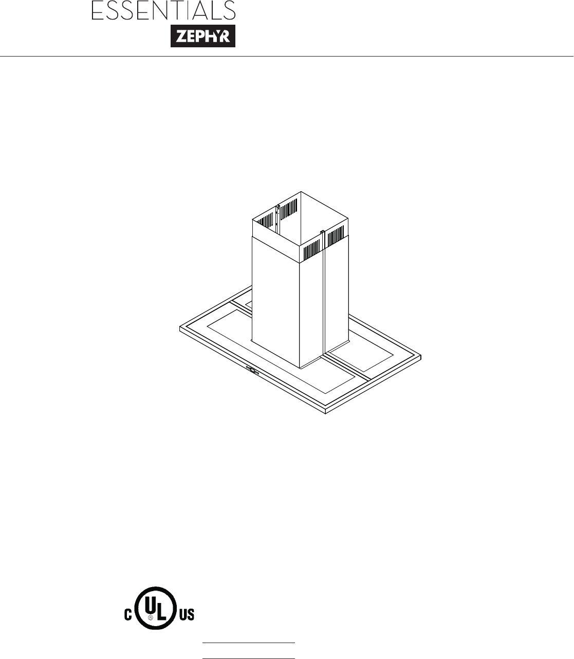
- Modena Island 1
- Table of Contents 3
- Important Safety Notice 4
- List of Materials 6
- 26” min 8
- 34” max 8
- WARNING FIRE HAZARD 9
- TOP of HOOD 10
- TOP SUPPORT FRAME 10
- PAPER TEMPLATE 11
- ELECTRONICS 13
- MOUNTING 13
- Charcoal Filter Replacements 15
- SURFACE MAINTENANCE: 18
- Troubleshooting 19
- Pressure (inAq) 20
- DESCRIPTION PART# 21
- 1-888-880-8368 22
- Limited Warranty 22
- Table des matières 25
- Mise en garde de sécurité 26
- Liste du matériel 28
- Subtotal column 1 = 29
- Subtotal column 2 = 29
- Total ductwork = 29
- CONDUIT D’AÉRATION 30
- Reprise 31
- DESSUS de la HOTTE 32
- CADRE DE FIXATION SUPÉRIEUR 32
- (vue du dessus) 32
- GABARIT EN PAPIER 33
- SUPPORT DE 35
- MONTAGE DU 35
- DISPOSITIF 35
- ÉLECTRONIQUE 35
- Touche de mise en 38
- Dépannage 41
- Schéma de câblage 42
- DESCRIPTION N 43
- DE PIÈCE 43
- Garantie limitée 44
Summary of Contents
Use, Care, and Installation GuideModel number: Serial Number: APR12.0401 © Zephyr Corporation Modena IslandZMD-M90ASZMD-E42ASwww.zephyronline.com
8www.zephyronline.comInstallation – Hood Specifi cationsFRONTSIDETOP of HOODTOP SUPPORT FRAME(top view)C/L11 3/16”11 3/8”5 1/4”1/2”11 5/8”5 7/8”STANDAR
9Installation – Mounting the HoodHood is intended to be mounted to a fi nished ceiling.1. Ceiling Preparation: Determine hood mounting location and tem
10www.zephyronline.comInstallation – Mounting the HoodFRONTFRONTFIG. C125. Lift support frame assembly up to the ceiling making sure the the word “fr
11Installation – Mounting the Hood7. Remove tape securing electronics mounting bracket to hood. (FIG. F, #1) Position electronics mounting bracket as
12www.zephyronline.comFIG. J21354Top duct coversTop support frameBottom duct coversBottom support frameThick trim piece (top)Thin trim piece (bottom)c
13Ductless recirculation is intended for applications where an exhaust duct work is not possible to be installed. When converted, the hood functions a
14www.zephyronline.comLights On/Dim/OffDisplay (speed level, delay off, filter clean/change,clean air)Adjust 6 Speed LevelsPower / Delay Off1 Power /
Features & Controls – User Interface15Mesh Filter Clean Indicator (always enabled) - After 30 hours of fan usage the Graphic and words “clean
16www.zephyronline.comSURFACE MAINTENANCE:Clean the hood surface periodically with hot soapy water and clean cotton cloth. Do not use corrosive or abr
17TroubleshootingTROUBLESHOOTING PROCEDURES FOR MODENA ISLANDIssue Cause What to doAfter installation, the unit doesn’t work.1. The power source is n
www.zephyronline.com
18www.zephyronline.comWiring & Fan Curve DiagramsTHERMALLY PROTECTED Fan: Max. 203W Lamp: Max. 3Wx4
List of Parts & Accessories19DESCRIPTION PART#Replacement PartsLight Bulb, LED 3W Z0B-0032Aluminum Mesh Filter 50200042Optional AccessoriesRe
1-888-880-8368STAPLE YOUR RECEIPT HERETO OBTAIN SERVICE UNDER WARRANTY OR FOR ANY SERVICE RELATED QUESTIONS, please call: Zephyr Corporation (refe
Guide d’utilisation, d’entretien et d’installationNuméro de modèle : _________________Numéro de série : _________________APR12.0401 © Zephyr Corpo
www.zephyronline.com
1MISE EN GARDE DE SÉCURITÉ ... 2-3LISTE DU MATÉRIEL ... 4INSTALLATIONFeuill
Mise en garde de sécurité LISEZ ET CONSERVEZ CES INSTRUCTIONS2www.zephyronline.comAVERTISSEMENTPOUR RÉDUIRE LES RISQUES D’INCENDIE OU DE DÉCHARGE ÉLEC
Mise en garde de sécurité3ATTENTIONPOUR RÉDUIRE LES RISQUES D’INCENDIE, N’UTILISEZ QUE DES CONDUITS D’AÉRATION EN MÉTAL.CET APPAREIL N’EST PAS CONÇU P
Liste du matériel4www.zephyronline.com(3) Capuchons de connexion (4) M6 x 1 -1/2” (vis à bois) (20) M4 x 8 (1) M4 x 12 (vis de sûreté) (14 ) M3 x 5 (
5Duct pieces To t a lEquivalent numberlength x used =3- 1/ 4” x 10”Rect.,straight1 Ft. x ( ) =Ft. 8” Round,straight1 Ft.
1SAFETY NOTICE ... 2-3LIST OF MATERIALS ...
Installation – Espace libre et hauteur de montage6www.zephyronline.com CONDUIT D’AÉRATIONUn conduit circulaire de 8” doit être utilisé pour assurer u
7AVERTISSEMENT DE RISQUE D’INCENDIEN’évacuez ou ne terminez JAMAIS l’échappement du conduit dans les espaces entre les murs, les vides sanitaires, le
8www.zephyronline.comInstallation – Spécifi cations de la hotteDEVANTCÔTÉDESSUS de la HOTTECADRE DE FIXATION SUPÉRIEUR(vue du dessus)L/C11 3/16”11 3/8”
9La hotte est conçue pour être installée à un plafond fi ni.1. Préparation du plafond : Déterminez l’emplacement pour l’installation de la hotte et col
10www.zephyronline.comInstallation – Montage de la hotteFRONTFRONTFIG. C215. Soulevez l’assemblage des cadres de fi xation vers le plafond en vous ass
117. Enlevez le ruban qui retient le support de montage du dispositif électronique à la hotte (FIG. F#1). Enlevez les trois vis du dessus du boîtier
12www.zephyronline.comFIG. J21354Pièces de recouvrement supérieuresCadre de fixation supérieurPièces de recouvrement inférieuresCadre de fixation infé
13La confi guration de reprise sans conduit a été conçue pour les applications où il est impossible d’installer un conduit d’aération. Lorsque transfor
14www.zephyronline.comLumières : Allumer/Veilleuse/ÉteindreAffichage (vitesse, arrêt automatique, nettoyage/changement des filtres, purification d’air
15Installation – Interface utilisateurIndicateur de nettoyage des filtres à tamis (toujours en fonction)- Après 30 heures d’utilisation du ventilateu
Important Safety NoticeREAD AND SAVE THESE INSTRUCTIONS2www.zephyronline.comWARNING TO REDUCE THE RISK OF FIRE OR ELECTRIC SHOCK, DO NOT USE THIS FAN
Troubleshooting16www.zephyronline.comENTRETIEN DES SURFACES:Nettoyez régulièrement les surfaces de la hotte avec de l’eau savonneuse chaude et un chif
17DépannagePROCÉDURES DE DÉPANNAGE POUR LA HOTTE MODENA ISLANDProblème Cause SolutionAprèsl’installation,l’appareil ne fonctionne pas.1. Le bloc d’al
18Schéma de câblage Max. 203W Max. 3Wx4 Total: Max. 215W @ 3.5A 120V 60Hz ZMD-M90/E42ASUUVWVWAC-N AC-LON/OFF
Listes des pièces et des accessoires19DESCRIPTION NO DE PIÈCEPièces de remplacementAmpoule DEL 3W Z0B-0032 Filtre à tamis en
AGRAFEZ VOTRE REÇU ICIPOUR OBTENIR DU SERVICE SOUS GARANTIE OU POUR TOUTE QUESTION LIÉE À L’ENTRETIEN, veuillez communiquer avec nous au 1-888-880-836
Important Safety Notice3WARNINGTO REDUCE THE RISK OF FIRE, USE ONLY METAL DUCTWORK.NOT FOR USE IN OUTDOOR COOKING ENVIRONMENTS.CAUTIONTo reduce risk o
List of Materials4www.zephyronline.com(3) Wire Nuts(4) M6 x 1-1/2” wood screws (1) M4 x 12 safety screw (14) M3 x 5 pan-headduct cover screws1 - Hard
5Duct pieces To t a lEquivalent numberlength x used =3- 1/ 4” x 10”Rect.,straight1 Ft. x ( ) =Ft. 8” Round,straight1 Ft.
Installation – Mounting Height & Clearance6www.zephyronline.comDUCTINGA minimum of 8” round duct is recommended to maintain maximum air fl ow effi c
7WARNING FIRE HAZARDNEVER exhaust air or terminate duct work into spaces between walls, crawl spaces, ceiling, attics or garages. All exhaust must be
More documents for Cooker hoods Zephyr ZMD-M90AS

Related products and manuals for Cooker hoods Zephyr ZMD-M90AS
 (48 pages)
 (28 pages)
(23 pages)
(28 pages)
(23 pages)
 (23 pages)
© 2020, manymanuals.com. All rights reserved. | 0.693 s |
 Manymanuals.com
 Manymanuals.de
 Manymanuals.fr
 Manymanuals.it
 Manymanuals.pl
 Manymanuals.cz
 Manymanuals.es
 Manymanuals-pt.com
Comments to this Manuals